1.Application scope
The contract between Fuzhou University and Tianshui Hongshan Testing Machine Company was signed in 2012.In 2013,the water and electricity supplying for this machine were finished, andthe main component and oil source of this machine arrived in Fuzhou University. In 2015, the installing job and the debugging job were completed, andthe system began to work.
20000kN Electro-hydraulic Servo Pressure-shear System can be used to test theloadingperformance forthebearingsand the short columns.
The system is able to test the mechanical performance of the earthquake-isolating rubber bearings, the ordinary rubber bearings for highway bridges, the pot rubber bearings for railway bridges, spherical rubber bearings, etc. It can also be used to test the products of rubber bearings to test their ultimate compressive strength, compressive elastic modulus, anti-shear elastic modulus, axial deformation of the pot rubber bearings, anti-coherence performance, friction coefficient, and performance under torsion, etc.
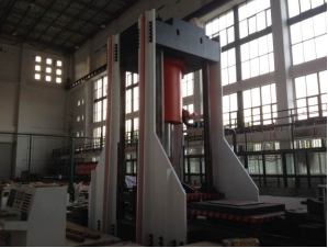
Fig.54 20000kN electro-hydraulic servo pressing-shearing system
2.System configurations
1.Vertical dynamic loading system.
It can be used to test the vertical loading performance ofthe earthquake-isolating rubber bearings and the ordinary rubber bearings, and the pressure performance of the short columns.
Maximum force: 20000kN for pressure, and 4000kN for tension.
Test space: 1200 mm.
Maximum size of test target:1800mm×1650mm.
The range of the vertical loading (press - press) frequency is 0 ~ 5 Hz.
When the vertical loading frequency is 2Hz, the maximum amplitude of displacement is 4mm.
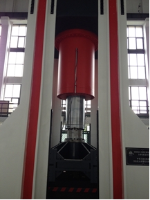
Fig 55 Vertical dynamic loading system
2.Horizontal dynamic loading system
It mainly can be used to test the horizontal loading performance ofthe earthquake-isolating rubber bearings and the ordinary rubber bearings, and the shear performance of the short columns.
Maximum force:3000kNfor pressure, and3000kNfor tension.
Maximum size of test target:1800mm×1650mm.
Piston Stroke:±600mm.
The range of the horizontal loading frequency is 0 ~ 5 Hz.
When the horizontal loading frequency is 2Hz, the maximum amplitude of displacement is 20mm. When the dynamic displacement is±600mm, the maximum loading frequency is 0.05Hz.
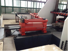
Fig 56 Horizontal dynamic loading system
3.Horizontal statistic loading system
It mainly can be used to test thestaticdouble-shear loading performance ofthe earthquake-isolating rubber bearings and the ordinary rubber bearings.
Maximum force: 0 kN ~ +4000 kN.
Maximum size of test target:1800mm×1650mm.
Piston stroke is 0 ~ 300 mm.
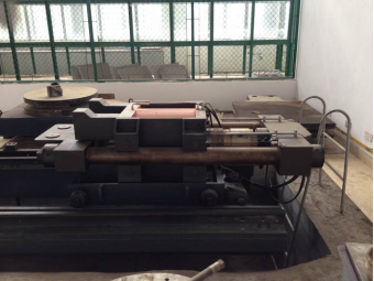
Fig 57 Horizontal statistic loading system
4.Torsion loading system
It mainly can be used to test the torsion loading performance ofthe earthquake-isolating rubber bearings and the ordinary rubber bearings.
Maximum test force:1500 kN;
Maximum size of test target:1800×1650(mm).
Maximum angle:0.06 rad.
5. Other configurations
Controler: Doli.
Pump: Parker.
Motor: ABB.
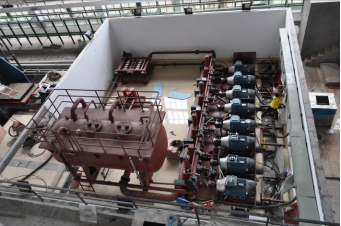
Fig 58 Oil source, pump and motor
3. Typical Testing models
3.1 RU-NC axial compressing short column ultimate bearing capacity test
In view of the durability problems for the bay bridges, especially for the bridge pier with the reinforced concrete structure, the chloride ion erosion by the seawater, led to the decrease of the structural performance. So the normal use and the operation security of the bridge was seriously affected. Therefore, the new structure, the reinforced high performance concrete (RUHPC) - plain concrete (NC) composite column (pier), was proposed.
In order to systematically study the mechanical properties of this new structure, especially the ultimate bearing capacity of RU-NC axial compressing short column, a scale model test and a finite element analysis of RU-NC axial compressing short column was carried out. The Pingtan Bridge was illustrated as the engineering background, and the mechanical performance and the ultimate bearing capacity of the RU-NC axial compressing short column were discussed. The 20000kN electro-hydraulic servo compressing-shearing system in Fuzhou University was adopted for loading.
Three parameters were designed in the test, the stirrup spacing, the thickness of UHPC and the steel fiber content respectively. The total number of the short column members were 18. The slender proportion of each RU-NC composite column in the experiment was 2.5, and each column was a short column (for the circular section,l0/dless than or equal to 7). The outer diameter of each column was D=305mm and the height is 762.5mm.The outer cylinder is UHPC120, and the inner core concrete is C40 plain concrete. Fig.1 is the test loading diagram of the RU-NC composite column. Fig.2 shows the test failure photos of the RU-NC composite column. Fig.3 and Fig.4 are load-strain curves and load-displacement curves of the RU-NC composite column respectively.
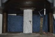
Fig.1 vbTest loading diagram
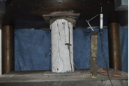
Fig.2 Failure photos
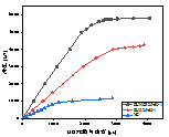
Fig.3 Load-strain curves
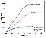
Fig.4 Load-displacement curves
3.2Ultrahigh performance mortar masonry axial compression test
The mortar joint is an important part in the masonry structure and the weak member in the masonry structure. However, at present, the strength of the cement-based cementitious materials is poor, and the durability is poor. The compressive strength of stone materials cannot be given full play to, resulting in the waste of resources. Aiming at this situation, a new type of masonry column with UHPM (UMC) was proposed to improve the mechanical properties of the Masonry structure.
In order to study the axial compression properties of the ultrahigh performance mortar masonry (UMC), the 20000 kN pressing-shearing system was used for the axial compressing test.The result was compared with traditional mortar masonry column (MC). The mechanical properties with UMC specimen, the failure mode and the ultimate bearing capacity were studied and discussed.
In this test, 7 groups of test parameters were designed, the mortar type, the mortar strength, the mortar joint thickness, the fiber type and the block flatness. The total number of the specimens is 21.The size of the specimens was 500mm*250mm*770mm. The mortar joint thickness was 10mm, and the stone used in the test was granite produced in the southeast coast.
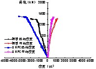
Fig.1 shows the failure pattern of MC specimen. Fig.2 shows the failure pattern of UMC specimen. Fig.3 and Fig.4 are the load-displacement curves and the load-strain curves of MC and UMC specimens respectively.
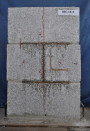
Fig.1 Failure pattern of MC specimen
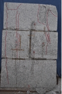
Fig.2 Failure pattern ofUMC
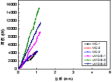
Fig.3 Load-displacement curves
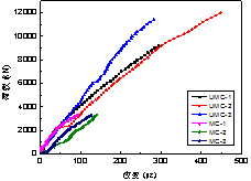
Fig.4 load-strain curves
3.3Axial compressing test on box-type concrete filled steel tube rigid frame column
In order to investigate the axial compressing performance and the failure mechanism of the box-type concrete filled steel tube rigid frame column (box-type CFST-RC column), the axial compressing capacity test on the box-type concrete filled steel tube rigid frame column was carried out, whose main parameters are the diameter of the steel tube and the thickness of the outer reinforced concrete.
The test included 6 box-type CFST-RC columns and the 4 corresponding CFST lattice columns. The main parameters considered in the test were the diameter of column pipe and the thickness of the outer reinforced concrete.
Specific steps for loading test components: Preloading is required before formal loading, which is aimed to eliminate the in homogeneity in the specimen. The next step is the centring, to make sure all parts can be in their normal working state, and to ensure that the measuring devices and instruments are also in their normal state. The preloading value is about 20% of the ultimate bearing capacity. After the preloading, the formal loading started, which was controlled by force step by step. The applied value of each step is about 1/10 of the predicted ultimate load. When the load is close to 80% of the predict ultimate bearing capacity, the loading mode is changed from load control to displacement control. If 1) the remaining bearing capacity is less than 80% of the ultimate bearing capacity, or 2) the concrete protective layer is peeled off in large, the specimen can be regarded as failed. Fig.1 is the photo of the axial compressing test and Fig.2 is test results.
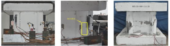
Fig.77 Photo of the axial compressing test
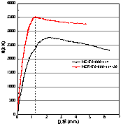
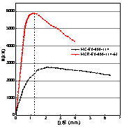
(a)MCR-E0-800-114-20 (b)MCR-E0-800-114-39 (c)MCR-E0-800-114-63
Fig.78 Test results
3.4Protective UHPC concrete-filled steel tube composite column compressing capacity test
The purpose of this test is to study the compressing capacity and the failure mode of the protective UHPC concrete-filled steel tube composite column (UCFST column), comparing with the composite concrete-filled steel tube column (RCFST column), and to study the differences in the compressing capacity and the failure mode.
According to the ideas that "outer diameter changes, inner diameter remains” and “inner diameter changes, outer diameter changes”, 9 UCFST short columns, 9 RCFST short columns with the same cross section as UCFST columns, 7 UCFST long columns, and 4 CFST short columns were designed and manufactured in this experiment. UCFST columns were loaded by the 20000kN pressing-shearing system. After the accurate alignment, preloading ensures that the specimen was in axial compressing state before the formal loading. The loading diagram is shown in Fig.79.
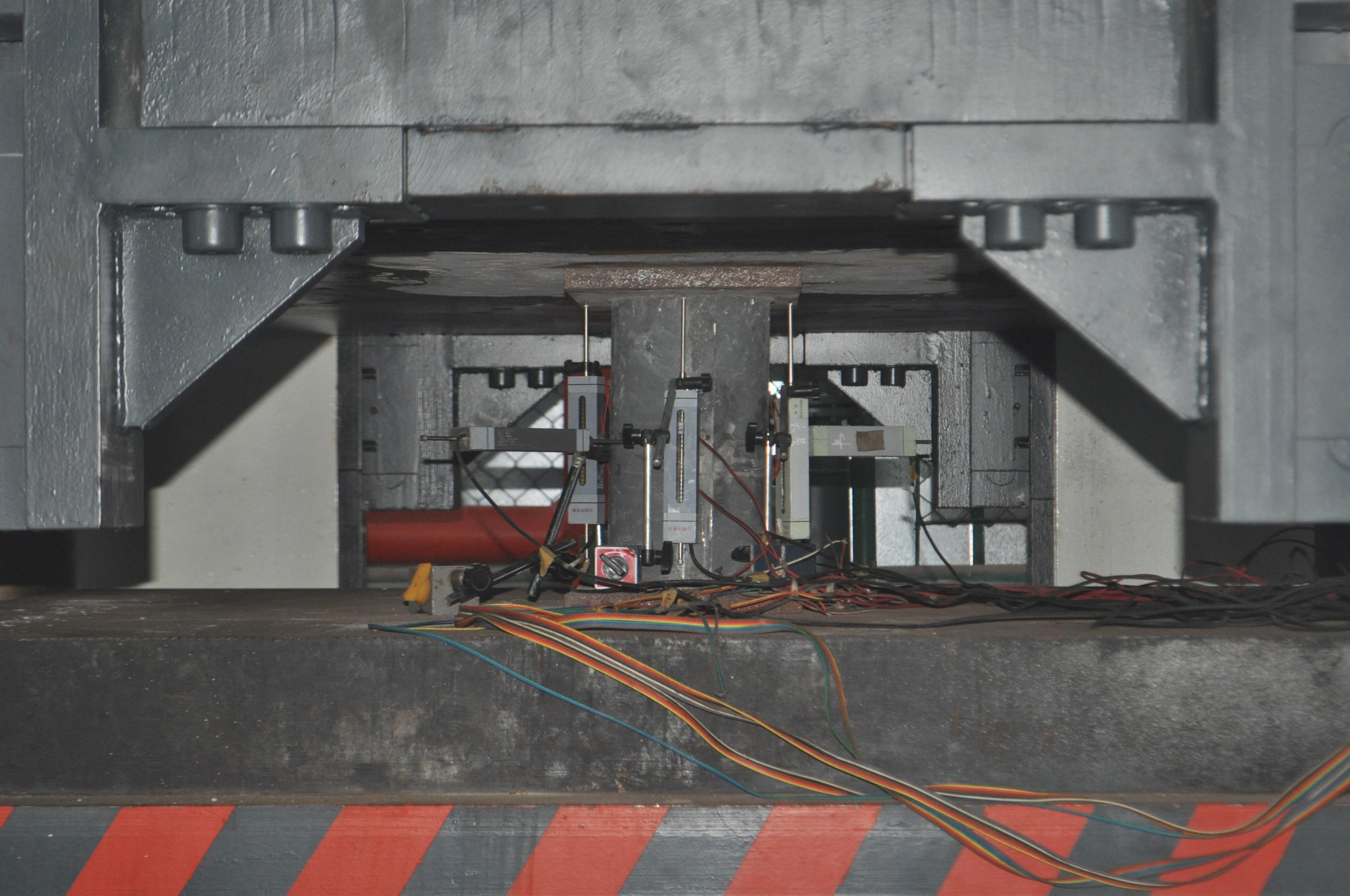
Fig.79 Loadingdiagram
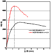
The specimens were loaded respectively according to their outer diameters alignments .The test results are shown in Fig. 80.

(a)Load-displacement curve (b)Load-strain curve
Fig. 80 Test results

