1. Application scope
The GCTS test system was purchased in 2016. The Fuzhou University spent nearly $3200000 on the system from the United states. In 2016 September, the equipment was transported to the Civil Engineering Institute, and the installation work was completed. At present, the equipment is in the experimental test stage.
The GCTS system is a set of closed loop digital servo control device, which is used for static and dynamic three axis test of rock, including rock three axis test, ultrasonic test, hydraulic fracturing test and Brazil split test. The large-scale system has the international advanced level and isalsothe largest set of similar equipment in the economic zone in the West Bank of the straits.
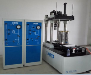
Fig.59 the GCTS Testing Systems
2. System configurations
1)Host frame
Equipment size: length2m, width1m, height3m.
Component size: diameter 50mm, height 100mm.
Frame structure: four column frame structure,thestiffnessis1750kN/mm and thedeformation is less than 1mm under 1500kN static load.
Axial loading: electro-hydraulic servo control.
Maximum static load: 1500kN.
Dynamic loading force: ± 820kN.
Dynamic loading frequency: 0-10HZ.
Loading travel:≥50mm.
The loading speed is more than 300mm/ minutes.
2)Boost controller
Pressure controlled range: 0~ 140Mpa
Resolution: 0.01MPa
Volume measurement of confining pressure: 600cc
Resolution: 0.01cc
Pore pressure volume measurement: 300cc
Resolution: 0.005cc.
Liquid container: 19L
Maximum heating temperature of pressure chamber: 150 C
Accuracy: 0.5 degrees C.
The pressure or volume is controlled by the system ofdigitally closed loop servo without low-frequency noise transmission.And the system is a twin piston turbocharging system.
3)Master controller and Test software
The main controller SCON-3000 microprocessor:1.8GHz
RAM:64Mb
hard disk memory:128Mb.
TheCATS software is a self-contained and self-contained module that includes function generation programs, data acquisition, and digital input/output units. The system is connected to the computer, complete data acquisition and control functions, and allows users to use structured Windows operations on the image user interface to freely program standard or complex test programs.
4) Other configurations
It includes hydraulic pumping station, air compressor, circulating water cooling system, etc.
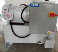
Fig.60 pumping station
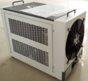
Fig.61 air compressor,
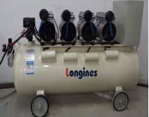
Fig.62 circulating water cooling system
3. Typical Testing models
3.1 Triaxial high temperature and high pressure test of rock
The rock triaxial test is a test for determining and studying rock deformation and strength characteristics under three-direction stress conditions. It is a relatively mature mechanical test method for geomaterials. Triaxial tests usually refer to conventional triaxial tests, ie σ2 = σ3 (as distinguished from true triaxial tests). This system meets the testing needs of rock or other material testing and research under high temperature/high pressure conditions.
This test mainly studies the uniaxial compressive strength, triaxial strength, post-destructive strength and bending load of high-strength concrete materials in various static loading tests. The compressive strength and tensile strength of high-strength concrete are measured. Shear strength, modulus of elasticity, bulk modulus, shear modulus, cohesion and internal friction angle, Poisson's ratio, permeability, and dynamic rock mechanics parameters.
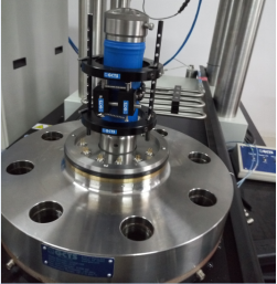
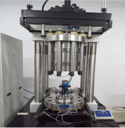
Fig.63 Sample device diagram
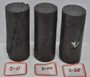
Fig.64 Triaxial failure test of high temperature and high pressure rock
3.2 Ultrasonic test
The ultrasonic test system mainly includes P wave and S wave ultrasonic sensors. It is capable of transmitting P and S waves. They are all built into the three-axis indenter, and the ultrasonic sensor crystal frequency is≥400kHz.
This experiment mainly studies the P wave and S wave velocity under the condition of surrounding rock stress under the tunnel depth of 200m. Dynamic elastic parameters such as Poisson's ratio, Young's modulus, bulk modulus and shear modulus are calculated. The rock ground stress is tested by the CVA radial wave velocity anisotropy test device, and the principal stress directions on the rock are determined by the P wave and S wave velocity at different angles and heights.
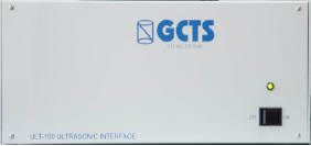
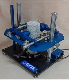
Fig.65 CVA radial wave velocity anisotropy measuring device
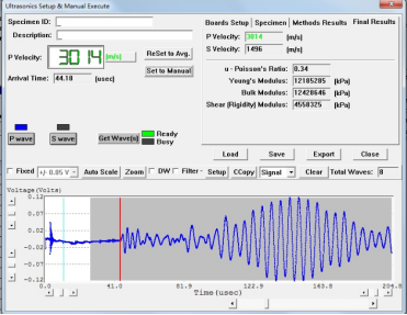
Fig.66 CVA radial wave velocity anisotropy measurement curve

